BACS Current Sensors - Generation 5

02 May 2024

-  AC/alternating current ripple measurement
-  Higher precision n Up to 8cm diameter of the Hall transducer
-  DIN rail mounting and flexible mounting
-  Differential current measurement

Current sensors play a central role in battery management systems (BMS), contributing significantly to increased operational safety and in the collection of data to calculate the SOH and SOC. They record the current flow of the battery, both direct current (DC) and alternating current (AC). Additionally, these measurements are used for:

  1. Error detection: Current sensors can detect anomalies in current flow that indicate battery failures, unbalanced strings, UPS or charger problems, and aging processes.
  2. Capacity measurement: Current sensors enable precise measurement of battery capacity by balancing “withdrawals” and “loading”. The measured values ​​are summed up and the full charge status can be determined precisely using battery balancing. This means that the user is shown a significantly more precise autonomy time or battery capacity than the UPS could provide, and thus the security that his UPS can actually achieve the desired autonomy time.
  3. Safety shutdown (optional): In critical situations, such as a short circuit or thermal runaway, BACS can detect this based on the current sensor readings and automatically switch off the battery, thus preventing a fire.
Picture from left to right: Generation 3, 4 and 5 current sensors. While the 3rd generation of sensors still had a closed ring through which power cables had to be pulled before crimping, the ring of Generation 4 (middle picture) could already be opened and so that it can be installed later. Like the 4th generation, Generation 5 is available for DIN rail mounting and as a flexible, free-hanging version.

More precise measurements of the 5th generation

The new 5th generation BACS current sensors measure more precisely than all their predecessors. In particular, the resolution in the low range (trickle charge <1A) has been significantly optimized, so that the measurement result of the battery capacity of BACS has been significantly improved.

New assembly variants

In addition, a new assembly variant is being added to the range with the 5th generation. The previous mounting variant for DIN rails is now also available in the 5th generation and bears the model identification CSHxxxx. The new “F” mounting variant is a flexible variant: The CHSxxxF is ideal for “hanging”, free assembly in confined spaces. Live cables are often laid in such a way that a DIN rail cannot be mounted. This would mean that the CSHxxxx with a DIN rail would hang freely in the air, which is technically not a problem, but not visually appealing.

It may happen that the cables do not fit through the sensor hole if it sits horizontally or vertically on a DIN rail, or the cables are routed in such a way that there is no space for the DIN housing. This mounting problem can be solved with the CSHxxxxF by hanging the sensor like a current clamp where there is space for it.

Image left: Sensor CSHxxx of generation 5 - Like its identical-looking predecessor of the 4th generation, this is mounted on a DIN rail.
Image center: Generation 5 sensor CSHxxx/F/Dmounted with (optional) DIN rail clips.
Image right: Generation 5 CSHxxxxF/D sensor without DIN rail clips is mounted hanging freely.

Easy retrofitting

A BACS system does not need current sensors to detect a discharge if a UPS connection has been set up via the COM port or via network (SNMP RFC 1628). In these cases, the detection of whether there is a power failure or not is reported by the UPS and not via the current sensor. This makes BACS significantly cheaper than the battery monitoring systems offered by all competitors because they generally require a current sensor for detection.

However, if the customer requires battery capacity (SoC) and/or thermal runaway detection, then the current sensors MUST be retrofitted for each battery string.
This is very easy to implement with all CS sensors with the “H” in the name. All CSH sensors are foldable - this folding technology allows the sensors to be retrofitted at any time without interruption. This represents a significant simplification compared to the Generation 3 CS sensors, where the power cables still had to be pulled completely through the rigid ring. However, the measurement accuracy was somewhat more precise with this closed version. To counteract this situation, we have developed Generation 5, which now achieves even more precise measurement results than those of the closed sensor of Generation 3.

Larger diameter up to 8cm

The CSHxxxxF is now also available in a version with a larger transducer diameter: All versions of the CSxxxx and CSHxxxx current sensors were previously available with a maximum diameter of 40mm. This ring diameter is sufficient for all common power cables in the EU, although cable diameters that are even thicker than 4cm can sometimes be found in power plants in the USA and Asia. We now offer a special version of the current sensor with an 8cm diameter:
The CSHxxxxF8 type is available as a 1000A sensor and is available for cables with a diameter of up to 80mm.

Image: CSH1000F8 with transducer for cables up to 80mm diameter

“Dual Use” - for both BACS as well as for SENSOR MANAGER

All sensors of the 4th and 5th generation can be used either for the SENSORMANAGER or for BACS. For BACS, the RJ10 BACS bus sockets are used on the right side, while the RJ12 sockets are used on the left side for the SENSORMANAGER.

Differential current input

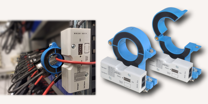
All 5th generation sensors have an additional input through which it is possible to connect the CSHxxxxD differential current sensor in order to detect any leaks between the DC input and DC output.
Differential currents should not occur in DC systems as there is a potential risk of getting an electric shock if touched, as the currents use other paths. This problem should be identified and corrected without exception to avoid injury, personal injury or even fatal accidents.
Generally, live parts in electrical devices are protected by personal protection or residual current circuit breakers, but this does not apply to UPS systems! Due to the system, no residual current switch is used there, so a “leak” can certainly lead to personal injury. The usual “workarounds” using an insulated battery rack etc. ensure safety, but do not rule out leakage current. In order to avoid personal injury and property damage, it is important to recognize these. Furthermore, residual currents are harmful to batteries, endanger the UPS technology and can lead to a fire. For this reason, the use of differential current sensors is required in many tenders in the USA and by the US authority NERC.